
Page 212 - Power Electronic Control in Electrical Systems
P. 212
//SYS21/F:/PEC/REVISES_10-11-01/075065126-CH006.3D ± 200 ± [177±262/86] 17.11.2001 10:22AM
200 Power electronic equipment
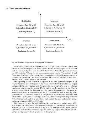
Fig. 6.25 Quadrants of operation of the single-phase half-bridge VSC.
The converter discussed here operates in all four quadrants of output voltage and
current as shown in Figure 6.25. There are two distinct modes of operation associated
with the transfer of power from the DC to the AC side. When the power flows from
the DC bus to the AC side, the converter operates as an inverter. The switches S 1 and
S 2 perform this function. In the case that the power is negative, which means power is
returned back to the DC bus from the AC side, the converter operates as a rectifier.
The diodes D 1 and D 2 perform this function.
The capability of the converter to operate in all four quadrants (Figure 6.25)
means that there is no restriction in the phase relationship between the AC output
voltage and the AC output current. The converter can therefore be used to exchange
leading or lagging reactive power. If the load is purely resistive and no filter is
attached to the output the diodes do not take part in the operation of the converter
and only real power is transferred from the DC side to the AC one. Under any other
power factor, the converter operates in a sequence of modes between a rectifier and
an inverter. The magnitude and angle of the AC output voltage with respect to the
AC output current control in an independent manner the real and reactive power
exchange between the DC and AC sides.
This converter is also the basic building block of any other switch-mode VSC.
Specifically, the combination of the switching blocks (S 1 and the antiparallel diode
D 1 ) and (S 2 and D 2 ) can be used as a leg to build three-phase and other types of
converters with parallel connected legs and other topologies. These types of con-
verters will be described in later sections of this chapter.