
Page 211 - Power Electronic Control in Electrical Systems
P. 211
//SYS21/F:/PEC/REVISES_10-11-01/075065126-CH006.3D ± 199 ± [177±262/86] 17.11.2001 10:22AM
Power electronic control in electrical systems 199
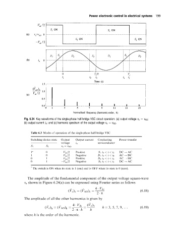
Fig. 6.24 Key waveforms of the single-phase half-bridge VSC circuit operation. (a) output voltage v o v AO ;
(b) output current i o ; and (c) harmonic spectrum of the output voltage v o v AO .
Table 6.3 Modes of operation of the single-phase half-bridge VSC
Switching device state Output Output current Conducting Power transfer
voltage i o semiconductor
S 1 S 2 v o v AO
1 0 V dc /2 Positive S 1 t 4 < t < t 5 DC ! AC
1 0 V dc /2 Negative D 1 t 3 < t < t 4 AC ! DC
0 1 V dc /2 Positive D 2 t 1 < t < t 2 AC ! DC
0 1 V dc /2 Negative S 2 t 2 < t < t 3 DC ! AC
* The switch is ON when its state is 1 (one) and is OFF when its state is 0 (zero).
The amplitude of the fundamental component of the output voltage square-wave
v o shown in Figure 6.24(a) can be expressed using Fourier series as follows
^ ^ 4 V dc
(V o ) (V AO ) (6:18)
1
1
2 p
The amplitude of all the other harmonics is given by
^
^ ^ 4 V dc (V o ) 1
(V o ) (V AO ) h 3, 5, 7, 9, ... (6:19)
h
h
2 p h h
where h is the order of the harmonic.