
Page 215 - Power Electronic Control in Electrical Systems
P. 215
//SYS21/F:/PEC/REVISES_10-11-01/075065126-CH006.3D ± 203 ± [177±262/86] 17.11.2001 10:22AM
Power electronic control in electrical systems 203
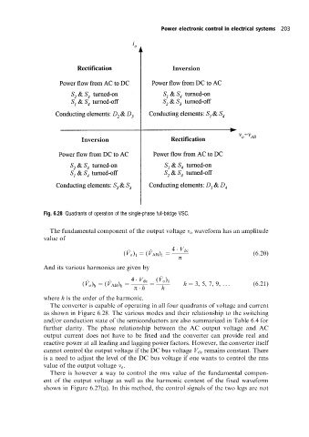
Fig. 6.28 Quadrants of operation of the single-phase full-bridge VSC.
The fundamental component of the output voltage v o waveform has an amplitude
value of
^ ^ 4 V dc
(V o ) (V AB ) p (6:20)
1
1
And its various harmonics are given by
^
(V o )
^ ^ 4 V dc 1
(V o ) (V AB ) p h h h 3, 5, 7, 9, ... (6:21)
h
h
where h is the order of the harmonic.
The converter is capable of operating in all four quadrants of voltage and current
as shown in Figure 6.28. The various modes and their relationship to the switching
and/or conduction state of the semiconductors are also summarized in Table 6.4 for
further clarity. The phase relationship between the AC output voltage and AC
output current does not have to be fixed and the converter can provide real and
reactive power at all leading and lagging power factors. However, the converter itself
cannot control the output voltage if the DC bus voltage V dc remains constant. There
is a need to adjust the level of the DC bus voltage if one wants to control the rms
value of the output voltage v o .
There is however a way to control the rms value of the fundamental compon-
ent of the output voltage as well as the harmonic content of the fixed waveform
shown in Figure 6.27(a). In this method, the control signals of the two legs are not