
Page 223 - Power Electronic Control in Electrical Systems
P. 223
//SYS21/F:/PEC/REVISES_10-11-01/075065126-CH006.3D ± 211 ± [177±262/86] 17.11.2001 10:23AM
Power electronic control in electrical systems 211
Specifically, the converter consists of four switches (S a1 , S a2 , S a3 , S a4 ) and the
antiparallel diodes (D a1 , D a2 , D a3 , D a4 ). Due to the nature of the leg being able to
generate a three-level voltage waveform between the points A and O, two DC bus
voltage sources of equal value are required. This can be accomplished with two equal
value capacitors C 1 and C 2 where the initial DC bus voltage V dc is split across to
make two voltage sources of V dc /2 value available.
In previous sections, the phase-shifted control method (Figures 6.29 and 6.30) for a
single-phase full-bridge VSC shown in Figure 6.26 was explained. The interesting
point of such a technique is the ability to control the output voltage and its harmo-
nics contents by adjusting the angle a (degrees) where the line-to-line waveform
becomes zero.
It has been introduced in the technical literature that the number of levels of the
voltage between the mid-point of the converter leg and the DC bus mid-point (line-
to-neutral voltage waveform) is used to classify a given multilevel topology. The
conventional three-phase VSC as shown in Figure 6.32 is then a two-level converter
since it is capable of producing a two-level waveform between the two points men-
tioned above.
To clamp the voltage, two extra clamping diodes D ca1 and D ca2 as shown in Figure
6.34 are required to connect the DC bus mid-point to the load applying zero volts.
They also allow the current to flow in either direction when the converter operates in
the free-wheeling mode (zero volts at the output). For this case the load can be
connected between the points A and O like the case of the single-phase half-bridge
VSC shown in Figure 6.23.
The control for the three-level half-bridge VSC is slightly different and will be
explained next. It can be confirmed with the assistance of Figures 6.34 and 6.35 that
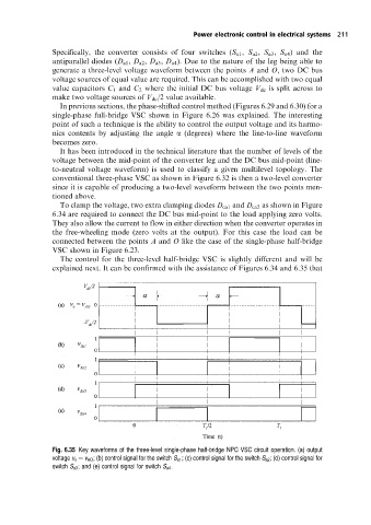
Fig. 6.35 Key waveforms of the three-level single-phase half-bridge NPC VSC circuit operation. (a) output
voltage v o v AO ; (b) control signal for the switch S a1 ; (c) control signal for the switch S a2 ; (d) control signal for
switch S a3 ; and (e) control signal for switch S a4 .