
Page 242 - Power Electronic Control in Electrical Systems
P. 242
//SYS21/F:/PEC/REVISES_10-11-01/075065126-CH006.3D ± 230 ± [177±262/86] 17.11.2001 10:23AM
230 Power electronic equipment
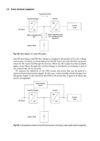
Fig. 6.53 Block diagram of a basic UPS system.
into DC providing a stiff DC bus voltage as an input to the inverter if it is of a voltage
source type. A battery is connected across the DC bus to provide the back up power
when the AC mains fail through the inverter. When the AC supply becomes available
again, power flows through the rectifier/charger to the battery to recharge it and to
the critical load via the inverter.
To increase the reliability of the UPS system, the power line can be used as a
separate bypass input power supply. In this case, a static transfer switch changes over
the power supply to the load from the UPS to the power line. Figure 6.54 shows the
circuit arrangement.
Fig. 6.54 Complementary functions for the UPS and the power line through a static transfer switch arrangement.