
Page 243 - Power Electronic Control in Electrical Systems
P. 243
//SYS21/F:/PEC/REVISES_10-11-01/075065126-CH006.3D ± 231 ± [177±262/86] 17.11.2001 10:23AM
Power electronic control in electrical systems 231
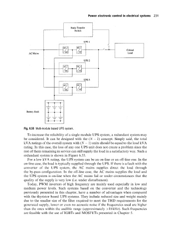
Fig. 6.55 Multi-module based UPS system.
To increase the reliability of a single module UPS system, a redundant system may
be considered. It can be designed with the (N 1) concept. Simply said, the total
kVA ratings of the overall system with (N 1) units should be equal to the load kVA
rating. In this case, the loss of any one UPS unit does not create a problem since the
rest of them remaining in service can still supply the load in a satisfactory way. Such a
redundant system is shown in Figure 6.55.
For a low kVA rating, the UPS system can be an on-line or an off-line one. In the
on-line case, the load is typically supplied through the UPS. If there is a fault with the
converter of the UPS system, the AC mains supplies direct the load through
the by-pass configuration. In the off-line case, the AC mains supplies the load and
the UPS system is on-line when the AC mains fail or under circumstances that the
quality of the supply is very low (i.e. under disturbances).
Today, PWM inverters of high frequency are mainly used especially in low and
medium power levels. Such systems based on the converter and the technology
previously presented in this chapter, have a number of advantages when compared
with the thyristor based UPS systems. They include reduced size and weight mainly
due to the smaller size of the filter required to meet the THD requirements for the
generated supply, lower or even no acoustic noise if the frequencies used are higher
than the ones within the audible range (approximately >18 kHz). Such frequencies
are feasible with the use of IGBTs and MOSFETs presented in Chapter 5.