
Page 305 - Power Electronic Control in Electrical Systems
P. 305
//SYS21/F:/PEC/REVISES_10-11-01/075065126-CH008.3D ± 293 ± [290±372/83] 17.11.2001 10:28AM
Power electronic control in electrical systems 293
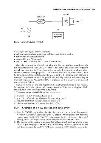
Fig. 8.1 Test circuit to be built in PSCAD.
. analogue and digital control functions
. AC machines, exciters, governors, stabilizers and inertial models
. meters and measuring functions
. generic DC and AC controls
. HVDC, SVC and other FACTS and CPcontrollers.
Once the construction of the circuit schematic diagram has been completed, it is
run using the module RunTime Executive. The simulation results to be captured
are selected using the RunTime Executive module. It is possible to observe these
results as the simulation progresses. This module allows for the use of sliders, push
buttons, dials and meters that permit the user to control the program in an interactive
manner. The process required for graphically building a circuit and simulating its
transient response in PSCAD/EMTDC is explained next in a very illustrative and
comprehensive fashion.
Figure 8.1 shows the one-line diagram of the electrical circuit used in this tutorial.
It comprises of a three-phase AC voltage source feeding into a six-pulse diode
rectifier, via a delta±star connected transformer.
The process may be divided into four major steps:
1. creation of a new project and data entry
2. generation of the circuit schematic diagram using Draft
3. transient simulation using RunTime Executive
4. plotting and analysis of results using MultiPlot.
8.3.1 Creation of a new project and data entry
1. Start the PSCAD graphical user interface by typing PSCAD in the shell command.
A window like the one shown in Figure 8.2 appears. At this point a new project is
created using the CREATE PROJECT option under the File Manager. Figure 8.2
already shows this project which in this exercise is called `ACSYSTEM'.
2. The next step is to create a study case that will contain all the files relating to the
circuit. Open the project `ACSYSTEM' by choosing the OPEN option under the
pull down menu in the `ACSYSTEM' icon. Using the CREATE CASE option under