Page 308 - Power Electronic Control in Electrical Systems
P. 308

//SYS21/F:/PEC/REVISES_10-11-01/075065126-CH008.3D ± 296 ± [290±372/83] 17.11.2001 10:28AM


               296 Transient studies of FACTS and Custom Power equipment

                                  Draft–(NONE), dir:/export/home/powered/oanaya/PSCAD/filenman/ACSYSTEM/SYSTEM_1
                           QUIT    ICON    HELP   OPTIONS  COMPILE  ABOUT  PSCAD version 2.00
                           FILE  SUBSYSTEM  PRINT  EDIT    VIEW   LIBRARY  Circuit Layout Module


                                                            1.0  0.1  1.0
                                                                                      A  B  C
                                                                                1.0    1.0  1.0
                                                                        F=300.0  F=300.0  0.1  1.0
                                                                                      A  B  C
                                                                                       RRL  RRL  RRL
                                                                  PASSIVE COMPONENTS
                                                                                         RL
                                                                                      1.0  RRL
                                                                         NODE  WIRE
                                                                         LABEL  LABEL

                                                                           Annotation  A  Harmonic
                                                                            Box        Current
                                                                                      B
                                                                                       Injection
                                                                                      C
                                                                          COMMENTS
                                                              BUS WORK     & LABELS   SOURCES
                                                                          A  B  C
                                                             A      A  A          A
                                                              Tmva=100.0  Tmva=100.0
                                                             B      B  B          B
                                                              #1  #2    #1      #3
                                                             C      C  C          C
                                                              230.0  230.0  230.0  230.0  230.0
                              Master component library "default" loaded.
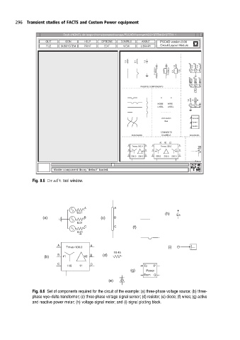
                      Fig. 8.5 Draft tool window.


                                           A           A
                                        0.01                                (h)  Ea
                          (a)              B      (c)  B
                                        0.01
                                           C           C       (f)
                                        0.01

                                A            A
                                   Tmva=100.0                                (i)
                                                       18.45
                          (b)   B  #1      #2  B  (d)
                                C            C
                                    115  11                        To        P
                                                              (g)   Power
                                                                   From    Q
                                                     (e)  D

                      Fig. 8.6 Set ofcomponents required for the circuit of the example: (a) three-phase voltage source; (b) three-
                      phase wye±delta transformer; (c) three-phase voltage signal sensor; (d) resistor; (e) diode; (f) wires; (g) active
                      and reactive power meter; (h) voltage signal meter; and (i) signal plotting block.
   303   304   305   306   307   308   309   310   311   312   313