
Page 309 - Power Electronic Control in Electrical Systems
P. 309
//SYS21/F:/PEC/REVISES_10-11-01/075065126-CH008.3D ± 297 ± [290±372/83] 17.11.2001 10:28AM
Power electronic control in electrical systems 297
A A
Tmva = 100.0
B
#1
Name Transformer Name T1
C Tmva 3 Phase Transformer MNA 100.0 MVA
115
f Base operation frequency 50 Hz
YD1 Winding #1 Type Y Delta
YD2 Winding #2 Type Y Delta
Lead Delta lags or leads Y Lags Leads
X1 Positive sequence leakage reactance 0.1 p.u.
Ideal Ideal Transformer Model No Yes
NLL No load losses 0.0 p.u.
Tap Tap changer winding None #1 #2
? PROCEED CANCEL
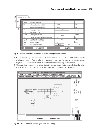
Fig. 8.7 Window to enter the parameters ofthe two-winding transformer model.
3. Select suitable parameters for each component. Choose the EDIT option in the
pull down menu of each selected component and set the appropriate parameters.
Figure 8.7 shows the window menu for the two-winding transformer.
4. Connect the components using the stretching wires. After completing the sche-
matic drawing, the circuit must look like the one shown in Figure 8.8.
Draft – sys_1. dir:~/PSCAD/fileman/ACSYSTEM/SYSTEM_1
QUIT ICON HELP OPTIONS COMPILE ABOUT PSCAD Version 2.00
LAYOUT SUBSYSTEM PRINT EDIT VIEW LIBRARY Circuit Layout Module
A B C
RRL RRL RRL
s s s
RL
1 1 3 5
s A A Tmva=100.0 A A A
0.01 Vab 0.001 18.45 1.0 RRL
s B B #1 #2 B B B s
0.01 0.001 s
s C C 115 11 C C C
0.01 0.001
Q From Power To P 4 2 6
Q P
A Harmonic
Vab current
B
Ia Injection
C
P
Q
SOURCES
AC system Subsystem: Basic
Fig. 8.8 Draft tool after completing the schematic drawing.