
Page 313 - Power Electronic Control in Electrical Systems
P. 313
//SYS21/F:/PEC/REVISES_10-11-01/075065126-CH008.3D ± 301 ± [290±372/83] 17.11.2001 10:28AM
Power electronic control in electrical systems 301
Fig. 8.12 Typical SVC's structures: (a) a TCR with a fixed capacitor; and (b) a TCR with a TSC.
the FC/TCR arrangement. In the case of switched elements (TSC/TCR), the
response time is usually 30±60 ms depending upon the SVC configuration and system
strength. In order to achieve such a high-speed response, it is necessary to properly
assess the type and size of the power components as well as the control scheme
according to the specific network configuration and operation requirements.
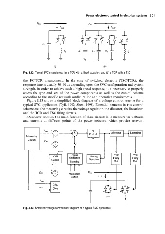
Figure 8.13 shows a simplified block diagram of a voltage control scheme for a
typical SVC application (Tyll, 1992; Shen, 1998). Essential elements in this control
scheme are: the measuring circuits, the voltage regulator, the allocator, the linearizer,
and the TCR and TSC firing circuits.
Measuring circuits. The main function of these circuits is to measure the voltages
and currents at different points of the power network, which provide relevant
Fig. 8.13 Simplified voltage control block diagram of a typical SVC application.