
Page 312 - Power Electronic Control in Electrical Systems
P. 312
//SYS21/F:/PEC/REVISES_10-11-01/075065126-CH008.3D ± 300 ± [290±372/83] 17.11.2001 10:28AM
300 Transient studies of FACTS and Custom Power equipment
File Manager
CASE PSCAD Version 2.00
File Manager Module
QUIT HELP OPTIONS HISTORY WASTE SYSTEM_1 NETWORK
DRAFT
RUNTIME
CIRCUIT DATA INFORMATION DSDYN DSOUT BATCH FILE OUTPUT T-LINE CABLE
FILE
sys_1.dft sys_1.dta sys_1.inf sys_1.dsd.f sys_1.dso.f sys_1.stb sys_1.out-1
RUNTIME
MULTIPLOT UNIPLOT
Process Icons
MULITPLOT
RUNTIME
MULTI PLOT
DRAFT RUN TIME
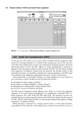
Fig. 8.11 File Manager window and files created for a given simulated circuit.
8.4 Static Var Compensator (SVC)
At this point in time, SVCs are the most widely installed FACTS equipment. They
mimic the working principles of a variable shunt susceptance and use fast thyristor
controllers with settling times of only a few fundamental frequency periods. From the
operational point of view, the SVC adjusts its value automatically in response to
changes in the operating conditions of the network. The SVC has the ability to either
draw capacitive or inductive current from the network. By suitable control of this
equivalent reactance, it is possible to regulate the voltage magnitude at the SVC point
of connection, thus enhancing significantly the power system's performance.
More specifically, as discussed in Chapter 3, voltage regulation at a key location of
the transmission system should provide the following benefits:
. prevention of large voltage variations
. prevention of voltage instability (voltage collapse)
. enlargement of transient (first swing) stability limits
. provision of power oscillations damping.
The SVC may be designed in many different ways. Figure 8.12 shows the schematic
diagrams of the most typical arrangements for continuously controlled SVCs i.e.
fixed capacitors (FC) with TCR and TSC with TCR. The thyristors are the con-
trollable elements enabling smooth control of the TCR when operated in the range of
90±180 . On the other hand, the TSC is a fast-switched element that achieves voltage
regulation in a stepwise fashion.
When the SVC is operated in a voltage control mode, it is the fastest thyristor-
controlled FACTS controller, with settling times of almost one period in the case of