
Page 307 - Power Electronic Control in Electrical Systems
P. 307
//SYS21/F:/PEC/REVISES_10-11-01/075065126-CH008.3D ± 295 ± [290±372/83] 17.11.2001 10:28AM
Power electronic control in electrical systems 295
File Manager
CASE PSCAD Version 2.00
File Manager Module
QUIT HELP OPTIONS HISTORY WASTE SYSTEM_1 NETWORK
DRAFT
T-LINE CABLE
RUNTIME
MULTIPLOT UNIPLOT
Process Icons
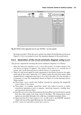
Fig. 8.4 PSCAD window appearing once the case `SYSTEM_1' has been opened.
the same as in step 2. Once the case is opened, the window looks like the one shown in
Figure 8.4. Now we proceed to draw the schematic diagram of the model circuit.
8.3.2 Generation of the circuit schematic diagram using Draft
The process required for drawing the circuit schematic diagram is as follows:
1. Select the action box labelled Draft to start the module. A window similar to the
one shown in Figure 8.5 appears. This window shows the Draft module bar of
menus, part of the drawing canvas and the library of components.
2. There is a pull down menu for each component in the library located at the right-
hand side of the screen. Select the COPY option under the pull down menu of the
required library component and drag it on to the work sheet. For this example, it
is necessary to copy the components shown in Figure 8.6 to the drawing canvas.
These include:
. Three-phase source model with built-in controls for adjusting the magnitude
and/or phase of the source.
. Three-phase, two-winding transformer model with built-in controls to define
transformer parameters such as capacity, operating frequency, winding data,
and saturation among others.
. Real/Reactive power meter that measures the three-phase real and/or reactive power
flow into three nodes from three network branches. The instantaneous power
signals are smoothed through a first order lag to simulate transducer delays.
. Signal plotting block that causes Draft to add code to the EMTDC program
which will record the signal flowing into the component.
. Wire connectors and label, a diode and a resistor.