
Page 317 - Power Electronic Control in Electrical Systems
P. 317
//SYS21/F:/PEC/REVISES_10-11-01/075065126-CH008.3D ± 305 ± [290±372/83] 17.11.2001 10:28AM
Power electronic control in electrical systems 305
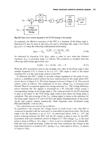
Fig. 8.16 Basic control scheme designed for the FC/TCR topology of the example.
As expected, the effective reactance of the SVC is a function of the firing angle a.
Equation 8.9 may be used to plot Q SVC (a) and to determine the angle a for which
Q SVC (a) 0, using the following fundamental relationship
Q SVC V 2 X C [2p a sin 2a] pX L (8:10)
bus
pX C X L
As indicated by Equation 8.10, Q SVC takes a value of zero when the effective
reactance X SVC is extremely large, i.e. infinite. This condition is satisfied when the
following relationship approaches zero
X C [2(p a) sin 2a] pX L ! 0 (8:11)
With the SVC parameters used in this example, the value of the firing angle a that
satisfies Equation 8.11 is found to be a 115 . This angle is used as the initial
condition for a in the open-loop control of the SVC.
To illustrate the SVC's ability to provide voltage regulation at the point of con-
nection, a simplified control scheme has been implemented for the single-phase SVC
circuit shown in Figure 8.14. The block diagram is shown in Figure 8.16. This control
scheme works as follows: The amplitude of the bus voltage V bus is measured and
filtered. Then it is compared against the voltage reference V ref . The voltage difference
(error) between the two signals is processed by a PI controller which causes a
corresponding change in the firing angle a. The value provided by the PI controller
is used as the input to the TCR firing angle control unit where the firing pulse is
calculated. The zero-crossing of the V bus voltage signal is taken as the reference for
the firing angle. Figures 8.17 and 8.18 show the digital implementation of the power
circuit and control scheme respectively. Both diagrams were developed using
PSCAD/EMTDC v3.04 for PCs.
Two experiments are carried out as follows:
In experiment 1 the constant AC voltage source V S feeds Load 1 only. The SVC is
connected in parallel with the load and it is controlled in open-loop mode. The firing
angle a for the thyristors is set at 115 . As mentioned above, with a 115 the
power exchange between the SVC and the AC system is close to zero for the SVC
parameters and load conditions shown in Figure 8.17. The voltage V rms at the load
point is close to 0.96 p.u. At a time t 0:6s, Load 2 is switched on by closing Brk,
with the load overall increasing. Under the new load conditions the voltage at the
load point drops by as much as 16%, giving a V rms value equal to 0.8 p.u., as shown
in Figure 8.19(a).