
Page 318 - Power Electronic Control in Electrical Systems
P. 318
//SYS21/F:/PEC/REVISES_10-11-01/075065126-CH008.3D ± 306 ± [290±372/83] 17.11.2001 10:28AM
306 Transient studies of FACTS and Custom Power equipment
Fig. 8.17 SVC power circuit implemented in PSCAD/EMTDC.
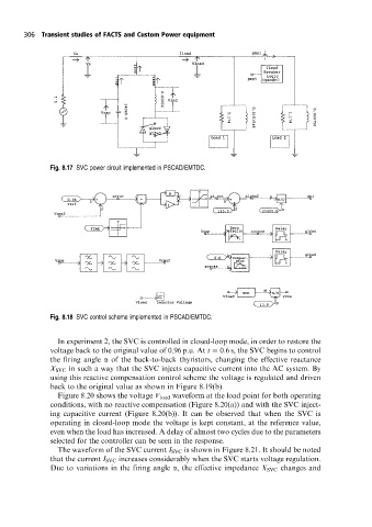
Fig. 8.18 SVC control scheme implemented in PSCAD/EMTDC.
In experiment 2, the SVC is controlled in closed-loop mode, in order to restore the
voltage back to the original value of 0.96 p.u. At t 0:6 s, the SVC begins to control
the firing angle a of the back-to-back thyristors, changing the effective reactance
X SVC in such a way that the SVC injects capacitive current into the AC system. By
using this reactive compensation control scheme the voltage is regulated and driven
back to the original value as shown in Figure 8.19(b).
Figure 8.20 shows the voltage V load waveform at the load point for both operating
conditions, with no reactive compensation (Figure 8.20(a)) and with the SVC inject-
ing capacitive current (Figure 8.20(b)). It can be observed that when the SVC is
operating in closed-loop mode the voltage is kept constant, at the reference value,
even when the load has increased. A delay of almost two cycles due to the parameters
selected for the controller can be seen in the response.
The waveform of the SVC current I SVC is shown in Figure 8.21. It should be noted
that the current I SVC increases considerably when the SVC starts voltage regulation.
Due to variations in the firing angle a, the effective impedance X SVC changes and