
Page 315 - Power Electronic Control in Electrical Systems
P. 315
//SYS21/F:/PEC/REVISES_10-11-01/075065126-CH008.3D ± 303 ± [290±372/83] 17.11.2001 10:28AM
Power electronic control in electrical systems 303
Fig. 8.14 Test system implemented to carry out time domain analysis ofthe SVC.
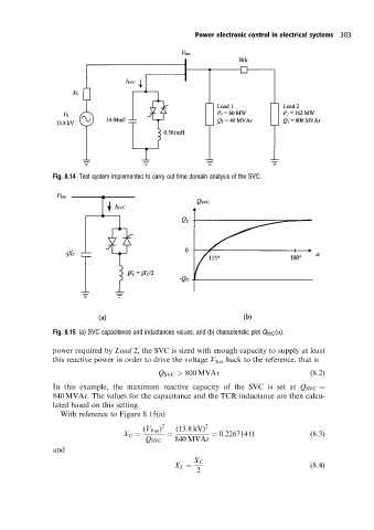
Fig. 8.15 (a) SVC capacitance and inductances values; and (b) characteristic plot Q SVC (a).
power required by Load 2, the SVC is sized with enough capacity to supply at least
this reactive power in order to drive the voltage V bus back to the reference, that is
Q SVC > 800 MVAr (8:2)
In this example, the maximum reactive capacity of the SVC is set at Q SVC
840 MVAr. The values for the capacitance and the TCR inductance are then calcu-
lated based on this setting.
With reference to Figure 8.15(a)
(V bus ) 2 (13:8 kV) 2
X C 0:226714
(8:3)
Q SVC 840 MVAr
and
X C
X L (8:4)
2