
Page 320 - Power Electronic Control in Electrical Systems
P. 320
//SYS21/F:/PEC/REVISES_10-11-01/075065126-CH008.3D ± 308 ± [290±372/83] 17.11.2001 10:28AM
308 Transient studies of FACTS and Custom Power equipment
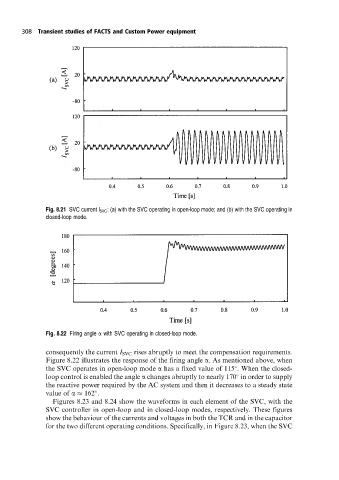
Fig. 8.21 SVC current l SVC : (a) with the SVC operating in open-loop mode; and (b) with the SVC operating in
closed-loop mode.
Fig. 8.22 Firing angle a with SVC operating in closed-loop mode.
consequently the current I SVC rises abruptly to meet the compensation requirements.
Figure 8.22 illustrates the response of the firing angle a. As mentioned above, when
the SVC operates in open-loop mode a has a fixed value of 115 . When the closed-
loop control is enabled the angle a changes abruptly to nearly 170 in order to supply
the reactive power required by the AC system and then it decreases to a steady state
value of a 162 .
Figures 8.23 and 8.24 show the waveforms in each element of the SVC, with the
SVC controller in open-loop and in closed-loop modes, respectively. These figures
show the behaviour of the currents and voltages in both the TCR and in the capacitor
for the two different operating conditions. Specifically, in Figure 8.23, when the SVC