
Page 324 - Power Electronic Control in Electrical Systems
P. 324
//SYS21/F:/PEC/REVISES_10-11-01/075065126-CH008.3D ± 312 ± [290±372/83] 17.11.2001 10:28AM
312 Transient studies of FACTS and Custom Power equipment
determines the direction of the current through the TCR and the capacitor, enabling
the TCSC to work as either a capacitive or an inductive reactance. In this mode,
the thyristor firing mechanism is controlled to vary the amount of effective react-
ance connected to the system (Jalali et al., 1994; Helbing and Karaday, 1994; Zhou,
Liang, 1999).
The series capacitive compensation is bypassed during minimum loading in order
to avoid transmission line overvoltages resulting from excessive capacitive effects in
the system. Conversely, series capacitive compensation is fully utilized during max-
imum loading. The purpose of this operating strategy is to increase the transfer of
power from generating sites to load centres, without overloading transmission lines.
8.5.1 Example 1
From the operational point of view, the TCSC shown in Figure 8.25 may be inter-
preted as a variable impedance which is a function of the thyristor firing angle a.In
most applications, the voltage across the capacitor V TCSC is taken as the reference
voltage for the purpose of determining the thyristor firing angle a. The thyristors are
fired when the capacitor voltage and current are opposite in polarity. This gives a
range of 90±180 for the firing angle of the forward-connected thyristor. Firing the
thyristors in this range results in a current flow through the inductor that opposes
that in the capacitor, creating a loop flow. This loop current increases the voltage
across the capacitor and the overall series compensation. This loop current increases
as a decreases from 180 to 90 .
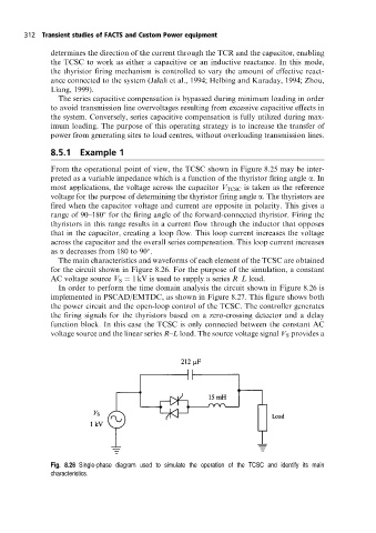
The main characteristics and waveforms of each element of the TCSC are obtained
for the circuit shown in Figure 8.26. For the purpose of the simulation, a constant
AC voltage source V S 1 kV is used to supply a series R±L load.
In order to perform the time domain analysis the circuit shown in Figure 8.26 is
implemented in PSCAD/EMTDC, as shown in Figure 8.27. This figure shows both
the power circuit and the open-loop control of the TCSC. The controller generates
the firing signals for the thyristors based on a zero-crossing detector and a delay
function block. In this case the TCSC is only connected between the constant AC
voltage source and the linear series R±L load. The source voltage signal V S provides a
Fig. 8.26 Single-phase diagram used to simulate the operation ofthe TCSC and identify its main
characteristics.