
Page 326 - Power Electronic Control in Electrical Systems
P. 326
//SYS21/F:/PEC/REVISES_10-11-01/075065126-CH008.3D ± 314 ± [290±372/83] 17.11.2001 10:28AM
314 Transient studies of FACTS and Custom Power equipment
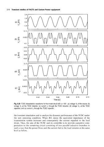
Fig. 8.28 TCSC characteristic waveforms for the model circuit with a = 130 . (a) voltage V S ofthe source; (b)
voltage V L at the TCSC inductor; (c) current I L through the TCSC inductor; (d) voltage V C at the TCSC
capacitor; and (e) current I C through the TCSC capacitor.
the transient simulation and to analyse the dynamic performance of the TCSC under
the new operating condition. When Brk opens the equivalent impedance of the
transmission system increases and consequently the current supplied to the load
drops. Thus, the aim of the TCSC and its controller is to provide capacitive com-
pensation to the remaining circuit consisting of two parallel inductive branches in
such a way that the power flows and the current fed to the load remains at the same
level as before.