
Page 331 - Power Electronic Control in Electrical Systems
P. 331
//SYS21/F:/PEC/REVISES_10-11-01/075065126-CH008.3D ± 319 ± [290±372/83] 17.11.2001 10:29AM
Power electronic control in electrical systems 319
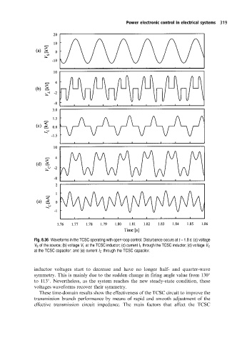
Fig. 8.36 Waveforms in the TCSC operating with open-loop control. Disturbance occurs at t = 1.8 s: (a) voltage
V S ofthe source; (b) voltage V L at the TCSC inductor; (c) current I L through the TCSC inductor; (d) voltage V C
at the TCSC capacitor: and (e) current I C through the TCSC capacitor.
inductor voltages start to decrease and have no longer half- and quarter-wave
symmetry. This is mainly due to the sudden change in firing angle value from 130
to 113 . Nevertheless, as the system reaches the new steady-state condition, these
voltages waveforms recover their symmetry.
These time-domain results show the effectiveness of the TCSC circuit to improve the
transmission branch performance by means of rapid and smooth adjustment of the
effective transmission circuit impedance. The main factors that affect the TCSC