
Page 334 - Power Electronic Control in Electrical Systems
P. 334
//SYS21/F:/PEC/REVISES_10-11-01/075065126-CH008.3D ± 322 ± [290±372/83] 17.11.2001 10:29AM
322 Transient studies of FACTS and Custom Power equipment
Fig. 8.39 Single-phase equivalent circuit ofa power system with a STATCOM controller.
This exchange can be used to replenish the internal losses of the VSC and to keep the
DC capacitor charged to the appropriate DC voltage, or to increase/decrease the
capacitor voltage and thereby the magnitude of the output voltage of the STAT-
COM.
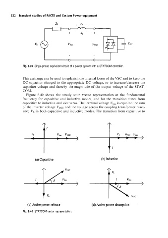
Figure 8.40 shows the steady state vector representation at the fundamental
frequency for capacitive and inductive modes, and for the transition states from
capacitive to inductive and vice versa. The terminal voltage V bus is equal to the sum
of the inverter voltage V VSC and the voltage across the coupling transformer react-
ance V L in both capacitive and inductive modes. The transition from capacitive to
Fig. 8.40 STATCOM vector representation.