
Page 337 - Power Electronic Control in Electrical Systems
P. 337
//SYS21/F:/PEC/REVISES_10-11-01/075065126-CH008.3D ± 325 ± [290±372/83] 17.11.2001 10:29AM
Power electronic control in electrical systems 325
Using the principle of harmonic reduction, the input and output of n basic six-pulse
inverters (which are operated with appropriate relative phase-displacements) can be
combined so as to obtain an overall P 6n multipulse structure. The frequencies of
the harmonics present in the output voltage and input current of this P-pulse inverter
are [Pk 1] f and Pkf, respectively. As can be seen, the harmonic spectrum improves
rapidly with increasing pulse number. In addition, the amplitude of these harmonics
is inversely related to the pulse number; that is, the amplitude of the k-th harmonic of
the output voltage waveform is proportional to 1/[Pk 1] and that of the DC supply
current to 1/Pk (Gyugyi, 1994).
Consequently, the FACTS STATCOM uses many six-pulse VSCs, appropriately
phase shifted, with their output combined electromagnetically to produce a nearly
sinusoidal resultant waveform. The pulse number of such an arrangement is generally
quoted as six times the number of basic inverters used, and provides an indication
of the level of harmonic reduction achieved. For transmission line applications, a
pulse number of 24 or higher is required to achieve adequate waveform quality
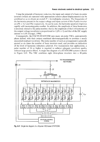
without large passive filters. A single line diagram of a STATCOM system is shown
in Figure 8.41. The VSC combines eight three-phase inverters into a 48-pulse
Fig. 8.41 Single-line diagram ofa 48-pulse VSC-based STATCOM.