
Page 338 - Power Electronic Control in Electrical Systems
P. 338
//SYS21/F:/PEC/REVISES_10-11-01/075065126-CH008.3D ± 326 ± [290±372/83] 17.11.2001 10:29AM
326 Transient studies of FACTS and Custom Power equipment
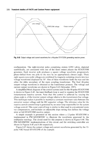
Line voltage
STATCOM voltage Output current
Fig. 8.42 Output voltage and current waveforms for a 48-pulse STATCOM generating reactive power.
configuration. The eight-inverter poles comprising sixteen GTO valves, depicted
symbolically, are associated with one of the three output phases the STATCOM
generates. Each inverter pole produces a square voltage waveform, progressively
phase-shifted from one pole to the next by an appropriately chosen angle. These
eight square-wave pole voltages are combined by magnetic summing circuits into two
voltage waveforms displaced by 30 . One of these waveforms feeds the wye and the
other the delta secondary of the main coupling transformer. The final 48-pulse
output voltage waveform is obtained at the transformer primary. The voltage and
current output waveforms are shown in Figure 8.42 (Schauder, 1997).
A simplified block diagram of the control system used for the 48-pulse STATCOM
is shown in Figure 8.43. An inner feedback loop is used to regulate the STATCOM
instantaneous reactive current. Note that this control is achieved by varying the
phase angle a, of the inverter output voltage relative to the transmission line voltage.
This technique makes it possible to maintain a constant maximum ratio between the
converter output voltage and the DC capacitor voltage. The reference value for the
reactive current control loop is generated by an outer loop responsible for the system
voltage control. This outer control loop is similar to that used in conventional static
var compensators, and includes an adjustable slope setting that defines the voltage
error at full STATCOM reactive output.
A simple example is presented in this section where a 12-pulse STATCOM is
implemented in PSCAD/EMTDC to illustrate the waveforms generated by the
multipulse topology. The circuit used for this purpose is shown in Figure 8.44. The
PSCAD/EMTDC implementations of this circuit and the switching controller are
shown in Figures 8.45 and 8.46 respectively.
Figure 8.47 shows the output voltage and current waveforms generated by the 12-
pulse VSC-based STATCOM of the example.