
Page 335 - Power Electronic Control in Electrical Systems
P. 335
//SYS21/F:/PEC/REVISES_10-11-01/075065126-CH008.3D ± 323 ± [290±372/83] 17.11.2001 10:29AM
Power electronic control in electrical systems 323
inductive mode occurs by changing the angle d from zero to a positive value. The
active power is transferred from the DC capacitor to the AC terminal and causes the
DC link voltage to drop. The transition from inductive to capacitive mode occurs by
changing the angle d from zero to a negative value. The active power is transferred
from the AC terminal to the DC capacitor and causes the DC link voltage to rise.
With reference to Figure 8.39 and Figure 8.40, the active and reactive power may
be expressed by the following equations
V bus V VSC
P sin d (8:12)
X L
V 2 bus V bus V VSC
Q cos d (8:13)
X L X L
In any practical STATCOM there are losses in the transformer windings and in the
converter switches. These losses consume active power from the AC terminals.
Accordingly, a small phase difference always exists between the VSC voltage and
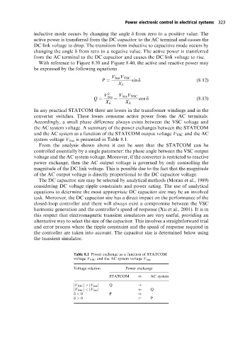
the AC system voltage. A summary of the power exchanges between the STATCOM
and the AC system as a function of the STATCOM output voltage V VSC and the AC
system voltage V bus is presented in Table 8.1.
From the analysis shown above it can be seen that the STATCOM can be
controlled essentially by a single parameter: the phase angle between the VSC output
voltage and the AC system voltage. Moreover, if the converter is restricted to reactive
power exchange, then the AC output voltage is governed by only controlling the
magnitude of the DC link voltage. This is possible due to the fact that the magnitude
of the AC output voltage is directly proportional to the DC capacitor voltage.
The DC capacitor size may be selected by analytical methods (Moran et al., 1989)
considering DC voltage ripple constraints and power rating. The use of analytical
equations to determine the most appropriate DC capacitor size may be an involved
task. Moreover, the DC capacitor size has a direct impact on the performance of the
closed-loop controller and there will always exist a compromise between the VSC
harmonic generation and the controller's speed of response (Xu et al., 2001). It is in
this respect that electromagnetic transient simulators are very useful, providing an
alternative way to select the size of the capacitor. This involves a straightforward trial
and error process where the ripple constraint and the speed of response required in
the controller are taken into account. The capacitor size is determined below using
the transient simulator.
Table 8.1 Power exchange as a function of STATCOM
voltage V VSC and the AC system voltage V bus
Voltage relation Power exchange
STATCOM , AC system
jV VSC j > jV bus j Q )
jV VSC j < jV bus j ( Q
d < 0 P )
d > 0 ( P