
Page 333 - Power Electronic Control in Electrical Systems
P. 333
//SYS21/F:/PEC/REVISES_10-11-01/075065126-CH008.3D ± 321 ± [290±372/83] 17.11.2001 10:29AM
Power electronic control in electrical systems 321
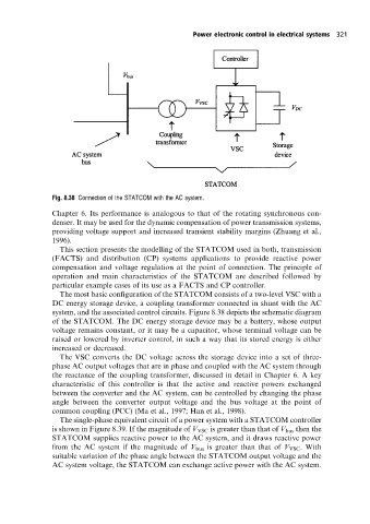
Fig. 8.38 Connection ofthe STATCOM with the AC system.
Chapter 6. Its performance is analogous to that of the rotating synchronous con-
denser. It may be used for the dynamic compensation of power transmission systems,
providing voltage support and increased transient stability margins (Zhuang et al.,
1996).
This section presents the modelling of the STATCOM used in both, transmission
(FACTS) and distribution (CP) systems applications to provide reactive power
compensation and voltage regulation at the point of connection. The principle of
operation and main characteristics of the STATCOM are described followed by
particular example cases of its use as a FACTS and CPcontroller.
The most basic configuration of the STATCOM consists of a two-level VSC with a
DC energy storage device, a coupling transformer connected in shunt with the AC
system, and the associated control circuits. Figure 8.38 depicts the schematic diagram
of the STATCOM. The DC energy storage device may be a battery, whose output
voltage remains constant, or it may be a capacitor, whose terminal voltage can be
raised or lowered by inverter control, in such a way that its stored energy is either
increased or decreased.
The VSC converts the DC voltage across the storage device into a set of three-
phase AC output voltages that are in phase and coupled with the AC system through
the reactance of the coupling transformer, discussed in detail in Chapter 6. A key
characteristic of this controller is that the active and reactive powers exchanged
between the converter and the AC system, can be controlled by changing the phase
angle between the converter output voltage and the bus voltage at the point of
common coupling (PCC) (Ma et al., 1997; Han et al., 1998).
The single-phase equivalent circuit of a power system with a STATCOM controller
is shown in Figure 8.39. If the magnitude of V VSC is greater than that of V bus then the
STATCOM supplies reactive power to the AC system, and it draws reactive power
from the AC system if the magnitude of V bus is greater than that of V VSC . With
suitable variation of the phase angle between the STATCOM output voltage and the
AC system voltage, the STATCOM can exchange active power with the AC system.