
Page 328 - Power Electronic Control in Electrical Systems
P. 328
//SYS21/F:/PEC/REVISES_10-11-01/075065126-CH008.3D ± 316 ± [290±372/83] 17.11.2001 10:28AM
316 Transient studies of FACTS and Custom Power equipment
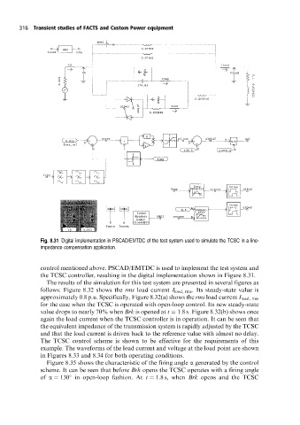
Fig. 8.31 Digital implementation in PSCAD/EMTDC ofthe test system used to simulate the TCSC in a line-
impedance compensation application.
control mentioned above. PSCAD/EMTDC is used to implement the test system and
the TCSC controller, resulting in the digital implementation shown in Figure 8.31.
The results of the simulation for this test system are presented in several figures as
follows: Figure 8.32 shows the rms load current I load, rms . Its steady-state value is
approximately 0.8 p.u. Specifically, Figure 8.32(a) shows the rms load current I load, rms
for the case when the TCSC is operated with open-loop control. Its new steady-state
value drops to nearly 70% when Brk is opened at t 1:8 s. Figure 8.32(b) shows once
again the load current when the TCSC controller is in operation. It can be seen that
the equivalent impedance of the transmission system is rapidly adjusted by the TCSC
and that the load current is driven back to the reference value with almost no delay.
The TCSC control scheme is shown to be effective for the requirements of this
example. The waveforms of the load current and voltage at the load point are shown
in Figures 8.33 and 8.34 for both operating conditions.
Figure 8.35 shows the characteristic of the firing angle a generated by the control
scheme. It can be seen that before Brk opens the TCSC operates with a firing angle
of a 130 in open-loop fashion. At t 1:8 s, when Brk opens and the TCSC