
Page 327 - Power Electronic Control in Electrical Systems
P. 327
//SYS21/F:/PEC/REVISES_10-11-01/075065126-CH008.3D ± 315 ± [290±372/83] 17.11.2001 10:28AM
Power electronic control in electrical systems 315
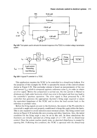
Fig. 8.29 Test system used to simulate the transient response ofthe TCSC in a medium-voltage transmission
system.
Fig. 8.30 A typical PI controller for a TCSC.
This application requires the TCSC to be controlled in a closed-loop fashion. For
the purposes of this example the TCSC is operated by means of the control scheme
shown in Figure 8.30. This particular scheme is based on measurements of the rms
load current I load which is compared against a reference value I ref in order to obtain
an error signal. Before the comparison is carried out, the rms current is filtered to
eliminate any high-order harmonic which may exist in the signal and that may lead to
the controller's spurious operation. The error signal is then processed by a PI
controller that generates the appropriate thyristor's firing angle required to adjust
the equivalent impedance of the TCSC and to drive the load current back to the
reference or prefault value.
Before the firing signals are sent to the thyristors, the output of the PI controller is
converted to angle units and properly conditioned to keep this angle within the limits.
This is also required to avoid operation near resonant points. The firing control unit
shown in Figure 8.30 includes the zero-crossing and delay functions. Also, the initial
condition for the firing angle a may be set in this unit. In these simulations the
thyristors are initially operated at a firing angle of a 130 , with no closed-loop
control. Once the system reaches steady state, an electrical disturbance is created by
opening Brk. Following this condition, the TCSC is operated with the closed-loop