
Page 330 - Power Electronic Control in Electrical Systems
P. 330
//SYS21/F:/PEC/REVISES_10-11-01/075065126-CH008.3D ± 318 ± [290±372/83] 17.11.2001 10:28AM
318 Transient studies of FACTS and Custom Power equipment
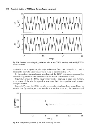
Fig. 8.34 Waveform of the voltage V load at the load point: (a) with TCSC in open-loop mode; and (b) TCSC in
closed-loop mode.
controller is set in operation, the angle a decreases from 130 to nearly 113 and it
then settles down to a new steady-state value of approximately 117 .
By decreasing a the equivalent impedance of the TCSC becomes more capacitive
thus reducing the inductive impedance of the overall transmission circuit.
Figure 8.36 shows the TCSC waveforms when it is operated in open-loop fashion.
As a result of the rise in equivalent reactance both the capacitor and inductor
voltages increase.
Figure 8.37 shows the TCSC waveforms operating in closed-loop mode. It can be
seen in this figure that just after the disturbance has occurred, the capacitor and
Fig. 8.35 Firing angle a processed by the TCSC closed-loop controller.