
Page 359 - Power Electronic Control in Electrical Systems
P. 359
//SYS21/F:/PEC/REVISES_10-11-01/075065126-CH008.3D ± 342 ± [290±372/83] 17.11.2001 10:29AM
342 Transient studies of FACTS and Custom Power equipment
8.8 Power Factor Corrector (PFC)
Power factor correction usually means the practice of generating reactive power as
close as possible to the load that requires it, rather than supplying it from a remote
power station. Most industrial loads have lagging power factors; that is, they absorb
reactive power. The load current therefore tends to be larger than is required to
supply the real power alone. Only the real power is ultimately useful in energy
conversion and the excess load current represents a waste to the consumer, who
has to pay not only for the excess cable capacity to carry it but also for the excess heat
loss produced in the supply cables. The supply utilities also have good reasons for not
transmitting unnecessary reactive power from generators to loads: their generators
and distribution networks cannot be used at full capacity, and the control of voltage
in the supply system can become more difficult. Supply tariffs to industrial customers
almost always penalize low power factor loads, and have done so for many years
(Miller, 1982).
These aspects and the current power quality regulations have led to the extensive
development of power factor correction systems which have lately been an active
research topic in power electronics. Conventional techniques for power factor correc-
tion involve the use of fixed capacitor banks and reactors with electromechanical
controllers. However, the advances in the power electronics technology have enabled
the development of new techniques and systems to improve the power factor. In this
point the research has been heavily focused on inverter applications (Mao, 1997).
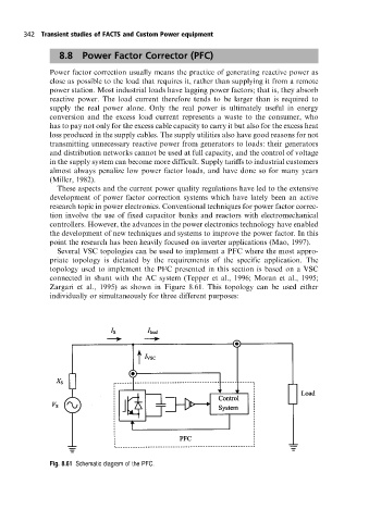
Several VSC topologies can be used to implement a PFC where the most appro-
priate topology is dictated by the requirements of the specific application. The
topology used to implement the PFC presented in this section is based on a VSC
connected in shunt with the AC system (Tepper et al., 1996; Moran et al., 1995;
Zargari et al., 1995) as shown in Figure 8.61. This topology can be used either
individually or simultaneously for three different purposes:
Fig. 8.61 Schematic diagram ofthe PFC.