
Page 361 - Power Electronic Control in Electrical Systems
P. 361
//SYS21/F:/PEC/REVISES_10-11-01/075065126-CH008.3D ± 344 ± [290±372/83] 17.11.2001 10:29AM
344 Transient studies of FACTS and Custom Power equipment
in a higher switching frequency than other techniques and the average varies with
operating conditions, thus resulting in additional stresses on switching devices and
difficulties in designing the appropriate filtering equipment.
2. Predictive current control with fixed switching frequency is based on prediction of
the current error from a load model. The advantages are speed and accuracy in
tracking the reference waveform; however, it is sensitive to parameter variations,
inaccuracies, and delays.
3. Indirect current control eliminates the need for current transducers and employs
a standard sinusoidal PWM pattern. However, system parameter values are
required and the stability region is more restricted as compared to the hysteresis
controller.
The current controller designed for the PFC presented in this section is developed
using a rotating (dq0) frame of reference that offers higher accuracy than the
stationary frame techniques. The block diagram of the overall control system is
shown in Figure 8.62.
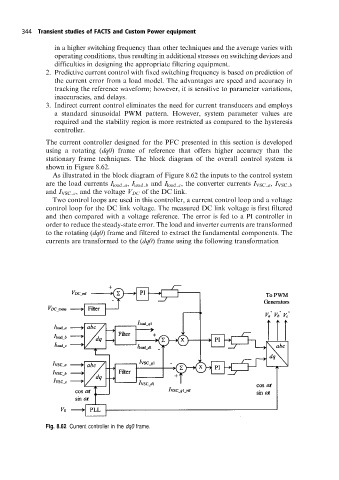
As illustrated in the block diagram of Figure 8.62 the inputs to the control system
are the load currents I load a , I load b and I load c , the converter currents I VSC a , I VSC b
and I VSC c , and the voltage V DC of the DC link.
Two control loops are used in this controller, a current control loop and a voltage
control loop for the DC link voltage. The measured DC link voltage is first filtered
and then compared with a voltage reference. The error is fed to a PI controller in
order to reduce the steady-state error. The load and inverter currents are transformed
to the rotating (dq0) frame and filtered to extract the fundamental components. The
currents are transformed to the (dq0) frame using the following transformation
Fig. 8.62 Current controller in the dq0 frame.