
Page 362 - Power Electronic Control in Electrical Systems
P. 362
//SYS21/F:/PEC/REVISES_10-11-01/075065126-CH008.3D ± 345 ± [290±372/83] 17.11.2001 10:29AM
Power electronic control in electrical systems 345
2 3
f a
f a 2 1 1/2 1/2
p
p
4 f b 5 (8:17)
f b 3 0 3/2 3/2
f c
where the function f in this case represents the instantaneous current. The transfor-
mation from the ab reference frame to the rotating (dq0) frame is achieved by means
of the following transformation
f d cos ot sin ot f a
(8:18)
f q sin ot cos ot f b
where o is the synchronous angular frequency of the mains supply. The DC compon-
ents in the rotating (dq0) frame f d and f q correspond to the positive sequence
fundamental components of f a and f b . Since the dq transformation is one that
converts frequency dependant signals into ones with constant value, an ideal three-
phase system yields constant f d and f q . The relation between the dq and active and
reactive components depends on the frame of reference selected.
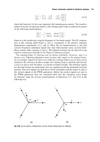
The rotating frame of reference can be chosen arbitrarily. However, once it is
chosen every following calculation must be done with respect to the selected frame.
As an example, Figure 8.63 shows two different rotating frames; any of these can be
selected as the reference. In this example, the rotating frame is selected such that the
q-axis is in phase with the phase a as shown in Figure 8.63(b). The reference signals
are the load current dq components that are compared with the measured converter
currents. The error signals are then fed to the PI controllers and the output is used as
the control signals in the PWM generators. Before the control signals are sent to
the PWM generators they are converted back into the stationary (abc) frame
of reference using the inverse transformation of Equations 8.17 and 8.18 in the
following way
Fig. 8.63 (a) An arbitrary rotating frame; and (b) chosen rotating frame of reference.