
Page 65 - Power Electronic Control in Electrical Systems
P. 65
//SYS21/F:/PEC/REVISES_10-11-01/075065126-CH002.3D ± 55 ± [31±81/51] 17.11.2001 9:49AM
Power electronic control in electrical systems 55
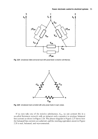
Fig. 2.24 Unbalanced delta-connected load with power-factor correction admittances.
Fig. 2.25 Unbalanced load corrected with unity power factor in each phase.
If we now take one of the resistive admittances, G ab , we can connect this in a
so-called Steinmetz networkwith an inductor and a capacitor to produce balanced
line currents as shown in Figure 2.26. The phasor diagram in Figure 2.27 shows how
the balanced line currents are achieved, and the resulting equivalent circuit in Figure
2.28 is real, balanced, and wye-connected.