
Page 61 - Power Electronic Control in Electrical Systems
P. 61
//SYS21/F:/PEC/REVISES_10-11-01/075065126-CH002.3D ± 51 ± [31±81/51] 17.11.2001 9:49AM
Power electronic control in electrical systems 51
2.9 Three-phase systems
Most power systems (from 415 V upwards) are three-phase systems. When the phases
are balanced, the phasor diagrams and equations of one phase represent all three
phases.
Why three-phase? The main reasons for having more than one phase are as
follows:
(a) better utilization of materials such as copper, iron, and insulation in lines, cables,
transformers, generators and motors
(b) constant power flow
(c) diversity and security of supply and
(d) `natural rotation', permitting the widespread use of AC induction motors.
2.9.1 Development of three-phase systems
To achieve `diversity' ± that is, the ability to supply different loads from different
circuits so that a failure in one circuit would not affect the others ± we can use
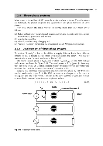
separate circuits or `phases' as shown in Figure 2.18.
The power in each phase is V ph I ph cos f where V ph and I ph are the RMS voltage
and current as shown in Figure 2.18. The total power is 3 V ph I ph cos f. Assuming
that the cable works at a certain current-density determined by its allowable tem-
perature rise, the total cross-section area of conductor is 6 A.
Suppose that the three phase currents are shifted in time phase by 120 from one
another as shown in Figure 2.19. The RMS currents are unchanged, as is the power in
each phase and the total power. The sum of the three currents is zero, and we can
express this in terms of instantaneous or phasor values
i a i b i c 0 and I a I b I c 0 (2:23)
Fig. 2.18 Three single-phase cables.