
Page 57 - Power Electronic Control in Electrical Systems
P. 57
//SYS21/F:/PEC/REVISES_10-11-01/075065126-CH002.3D ± 47 ± [31±81/51] 17.11.2001 9:49AM
Power electronic control in electrical systems 47
2.8 Control of power and frequency
In power systems it is essential to keep the frequency and the voltage close to their
rated values. The frequency is controlled by controlling the balance between the
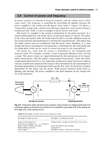
power supplied to the system and the power taken from it. Figure 2.16 shows a
transmission system with a prime mover driving a generator, and a motor driving a
mechanical load. Table 2.5 gives examples of prime movers and loads.
The power P in supplied to the system is determined by the prime mover(s). In a
steam-turbine generator, the steam valves are the main means of control. Of course,
if the valves are opened wide, the boiler must be able to provide sufficient steam (at
the correct pressure and temperature) to develop the required power. This means that
the boiler control must be coordinated with the steam valves. Similarly, in a wind
turbine the power transmitted to the generator is determined by the wind speed and
the blade pitch, which can be varied to control the power to the required level.
The power P out taken from the system is determined by the mechanical and
electrical loads. For example, consider a direct-connected induction motor driving
a pump. The motor rotates at a speed determined by the intersection of its torque/
speed characteristic with the pump's torque/speed characteristic. Since the motor
torque/speed characteristic is very steep near synchronous speed, the motor tends to
run near synchronous speed and the torque is then determined by the requirements of
the pump (depending on the pressure head and the flow rate). So the power is jointly
determined by the pump and the motor. With passive electrical loads (such as
lighting and heating), the power supplied to the load depends on the voltage and
the load impedance.
Fig. 2.16 Transmission system with prime mover, generator, motor and load. The voltages at both ends of the
transmission system are assumed to be controlled, so the symbol E is used instead of V. At the sending end,
the voltage is E s ; at the receiving end, E r .
Table 2.5 Examples of prime movers and mechanical loads
Examples of prime movers Examples of mechanical loads
Steam turbine-generator Pumps (water, sewage, process fluids, foods, etc.)
(coil, oil, gas, nuclear, etc. ± i.e. `thermal')
Hydro-electric turbine generator Fans and blowers (air-moving)
Wind turbine generator Compressors
Diesel engine Machinery, hoists, conveyors, elevators