
Page 52 - Power Electronic Control in Electrical Systems
P. 52
//SYS21/F:/PEC/REVISES_10-11-01/075065126-CH002.3D ± 42 ± [31±81/51] 17.11.2001 9:49AM
42 Power systems engineering ± fundamental concepts
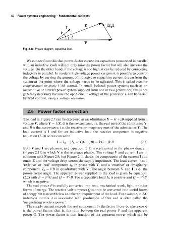
Fig. 2.10 Phasor diagram, capacitive load.
We can see from this that power-factor correction capacitors (connected in parallel
with an inductive load) will not only raise the power factor but will also increase the
voltage. On the other hand, if the voltage is too high, it can be reduced by connecting
inductors in parallel. In modern high-voltage power systems it is possible to control
the voltage by varying the amount of inductive or capacitive current drawn from the
system at the point where the voltage needs to be adjusted. This is called reactive
compensation or static VAR control. In small, isolated power systems (such as an
automotive or aircraft power system supplied from one or two generators) this is not
generally necessary because the open-circuit voltage of the generator E can be varied
by field control, using a voltage regulator.
2.6 Power factor correction
The load in Figure 2.7 can be expressed as an admittance Y G jB supplied from a
voltage V, where Y 1/Z. G is the conductance, i.e. the real part of the admittance Y,
and B is the susceptance, i.e. the reactive or imaginary part of the admittance Y. The
load current is I and for an inductive load the reactive component is negative
(equation (2.3)) so we can write
I I R jI X V(G jB) VG jVB (2:8)
Both V and I are phasors, and equation (2.8) is represented in the phasor diagram
(Figure 2.11) in which V is the reference phasor. The voltage V and current I are in
common with Figure 2.9, but Figure 2.11 shows the components of the current I and
omits E and the voltage drop across the supply impedance. The load current has a
`resistive' or `real' component I R in phase with V, and a `reactive' or `imaginary'
component, I X VB in quadrature with V. The angle between V and I is f, the
power-factor angle. The apparent power supplied to the load is given by equation.
2
2
2
(2.2) with P V G and Q V B. For a capacitive load I X is positive and Q V B,
which is negative.
The real power P is usefully converted into heat, mechanical work, light, or other
forms of energy. The reactive volt±amperes Q cannot be converted into useful forms
of energy but is nevertheless an inherent requirement of the load. For example, in AC
induction motors it is associated with production of flux and is often called the
`magnetizing reactive power'.
The supply current exceeds the real component by the factor 1/ cos f, where cos f
is the power factor: that is, the ratio between the real power P and the apparent
power S. The power factor is that fraction of the apparent power which can be