
Page 51 - Power Electronic Control in Electrical Systems
P. 51
//SYS21/F:/PEC/REVISES_10-11-01/075065126-CH002.3D ± 41 ± [31±81/51] 17.11.2001 9:49AM
Power electronic control in electrical systems 41
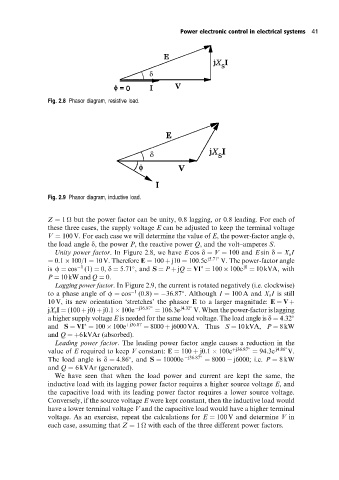
Fig. 2.8 Phasor diagram, resistive load.
Fig. 2.9 Phasor diagram, inductive load.
Z 1
but the power factor can be unity, 0.8 lagging, or 0.8 leading. For each of
these three cases, the supply voltage E can be adjusted to keep the terminal voltage
V 100 V. For each case we will determine the value of E, the power-factor angle f,
the load angle d, the power P, the reactive power Q, and the volt±amperes S.
Unity power factor. In Figure 2.8, we have E cos d V 100 and E sin d X s I
0:1 100/1 10V. Therefore E 100 j10 100:5e j5:71 V. The power-factor angle
j0
is f cos 1 (1) 0, d 5:71 ,and S P jQ VI 100 100e 10kVA, with
P 10kW and Q 0.
Lagging power factor. In Figure 2.9, the current is rotated negatively (i.e. clockwise)
to a phase angle of f cos 1 (0:8) 36:87 . Although I 100 A and X s I is still
10 V, its new orientation `stretches' the phasor E to a larger magnitude: E V
jX s I (100 j0) j0:1 100e j36:87 106:3e j4:32 V. When the power-factor is lagging
a higher supply voltage E is needed for the same load voltage. The load angle is d 4:32
and S VI 100 100e j36:87 8000 j6000VA. Thus S 10kVA, P 8kW
and Q 6kVAr (absorbed).
Leading power factor. The leading power factor angle causes a reduction in the
value of E required to keep V constant: E 100 j0:1 100e j36:87 94:3e j4:86 V.
The load angle is d 4:86 , and S 10000e j36:87 8000 j6000; i.e. P 8kW
and Q 6 kVAr (generated).
We have seen that when the load power and current are kept the same, the
inductive load with its lagging power factor requires a higher source voltage E, and
the capacitive load with its leading power factor requires a lower source voltage.
Conversely, if the source voltage E were kept constant, then the inductive load would
have a lower terminal voltage V and the capacitive load would have a higher terminal
voltage. As an exercise, repeat the calculations for E 100 V and determine V in
each case, assuming that Z 1
with each of the three different power factors.