
Page 49 - Power Electronic Control in Electrical Systems
P. 49
//SYS21/F:/PEC/REVISES_10-11-01/075065126-CH002.3D ± 39 ± [31±81/51] 17.11.2001 9:49AM
Power electronic control in electrical systems 39
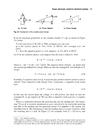
Fig. 2.6 Development of the complexpower triangle.
S can be expressed graphically as the complex number P jQ, as shown in Figure
2.6, where
P is the real power in W, kW or MW, averaged over one cycle
Q is the reactive power in VAr, kVAr, or MVAr, also averaged over one
cycle 6
S jSj is the apparent power or `volt±amperes', in VA, kVA or MVA 7
Let V be the reference phasor, and suppose that the load is inductive. Then
I Ie jf I cos f jI sin f (2:3)
where f tan 1 (X/R) tan 1 (Q/P). The negative phase rotation jf means that
the current lags behind the voltage. When we take the conjugate I and multiply by V
we get
P VI cos f and Q VI sin f (2:4)
Evidently P is positive and so is Q. A load that has positive reactive power is said to
`absorb' VArs. Inductive loads absorb VArs. Conversely, a capacitive load would
have
I Ie jf I cos f jI sin f (2:5)
In this case the current leads the voltage. P is still positive, but when we take the
conjugate I we get negative Q. We say that a capacitive load generates or supplies
VArs.
There is a distinction between the receiving end and the sending end. The expres-
sion `VI cos f' is correctly interpreted as power absorbed by the load at the receiving
end. But at the sending end the generated power P is supplied to the system, not
absorbed from it. The distinction is that the sending end is a source of power, while
the receiving end is a sink. In Figure 2.5, for example, both P s E s I cos f and
s
6
VAr `volt±amperes, reactive'
7
Although S is a complex number, it is not a phasor quantity. The power triangle merely represents the
relationship between P, Q, , and the apparent power S. Note that P, Q, and S are all average quantities
(averaged over one cycle); they are not rms quantities. On the other hand V and I are rms quantities.