
Page 53 - Power Electronic Control in Electrical Systems
P. 53
//SYS21/F:/PEC/REVISES_10-11-01/075065126-CH002.3D ± 43 ± [31±81/51] 17.11.2001 9:49AM
Power electronic control in electrical systems 43
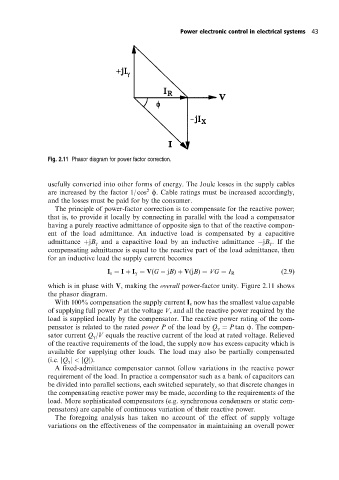
Fig. 2.11 Phasor diagram for power factor correction.
usefully converted into other forms of energy. The Joule losses in the supply cables
2
are increased by the factor 1/ cos f. Cable ratings must be increased accordingly,
and the losses must be paid for by the consumer.
The principle of power-factor correction is to compensate for the reactive power;
that is, to provide it locally by connecting in parallel with the load a compensator
having a purely reactive admittance of opposite sign to that of the reactive compon-
ent of the load admittance. An inductive load is compensated by a capacitive
admittance jB g and a capacitive load by an inductive admittance jB g . If the
compensating admittance is equal to the reactive part of the load admittance, then
for an inductive load the supply current becomes
I s I I g V(G jB) V(jB) VG I R (2:9)
which is in phase with V, making the overall power-factor unity. Figure 2.11 shows
the phasor diagram.
With 100% compensation the supply current I s now has the smallest value capable
of supplying full power P at the voltage V, and all the reactive power required by the
load is supplied locally by the compensator. The reactive power rating of the com-
pensator is related to the rated power P of the load by Q g P tan f. The compen-
sator current Q g /V equals the reactive current of the load at rated voltage. Relieved
of the reactive requirements of the load, the supply now has excess capacity which is
available for supplying other loads. The load may also be partially compensated
(i.e. jQ g j < jQj).
A fixed-admittance compensator cannot follow variations in the reactive power
requirement of the load. In practice a compensator such as a bankof capacitors can
be divided into parallel sections, each switched separately, so that discrete changes in
the compensating reactive power may be made, according to the requirements of the
load. More sophisticated compensators (e.g. synchronous condensers or static com-
pensators) are capable of continuous variation of their reactive power.
The foregoing analysis has taken no account of the effect of supply voltage
variations on the effectiveness of the compensator in maintaining an overall power