
Page 50 - Power Electronic Control in Electrical Systems
P. 50
//SYS21/F:/PEC/REVISES_10-11-01/075065126-CH002.3D ± 40 ± [31±81/51] 17.11.2001 9:49AM
40 Power systems engineering ± fundamental concepts
Table 2.4 Generating and absorbing reactive power: sinkand source
conventions
Lagging PF (I lags V) Leading PF (I leads V)
Load (sink) Q r > 0 Absorbing VArs Q r < 0 Generating VArs
Generator (source) Q s > 0 Generating VArs Q s < 0 Absorbing VArs
P r E r I cos f are positive, supplied to the system at the sending end and taken from
r
it at the receiving end. 8
A similar distinction arises with reactive power. The receiving end in Figure 2.5
evidently has a lagging power factor and is absorbing VArs. The sending end has a
leading power factor and is absorbing VArs. In Figure 2.9, the power factor is lagging
at both the generator and the load, but the load is absorbing VArs while the
generator is generating VARs. These conventions and interpretations are summar-
ized in Table 2.4.
Note that
Q P
tan f and cos f p (2:6)
P P Q 2
2
where cos f is the power factor.
Remember that phasors apply only when the voltage and currents are purely
sinusoidal, and this expression for power factor is meaningless if either the voltage
or current waveform is non-sinusoidal. A more general expression for power factor
with non-sinusoidal current and waveforms is
Average Power
PF (2:7)
RMS volts RMS amps
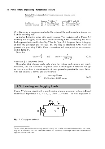
2.5 Leading and lagging loads
Figure 2.7 shows a circuit with a supply system whose open-circuit voltage is E and
short-circuit impedance is Z s 0 jX s , where X s 0:1
. The load impedance is
Fig. 2.7 AC supply and load circuit.
8
For a source, the arrows representing positive voltage and current are in the same direction. For a sink,
they are in opposite directions. This convention is not universal: for example, in German literature the
opposite convention is used.