
Page 46 - Power Electronic Control in Electrical Systems
P. 46
//SYS21/F:/PEC/REVISES_10-11-01/075065126-CH002.3D ± 36 ± [31±81/51] 17.11.2001 9:49AM
36 Power systems engineering ± fundamental concepts
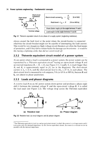
Fig. 2.1 The Âvenin equivalent circuit of one phase of a supply system (neglecting resistance).
always exceed the fault level at the point where the circuit-breaker is connected ±
otherwise the circuit-breaker might not be capable of interrupting the fault current.
This would be very dangerous: high-voltage circuit-breakers are often the final means
of protection, and if they fail to isolate faults the damage can be extreme ± it would be
like having a lightning strike that did not switch itself off.
Â
2.3.2 Thevenin equivalent circuit model of a power system
At any point where a load is connected to a power system, the power system can be
4
represented by a The  venin equivalent circuit having an open-circuit voltage E and
an internal impedance Z s R s jX s (see Figure 2.1). Usually X s is much bigger than
R s and Z s is approximately equal to jX s (as in the diagrams). The short-circuit
2
current is I sc E/X s and the short-circuit level is EI sc E /X s in each phase. The
short-circuit level is measured in volt-amperes, VA (or kVA or MVA), because E and
I sc are almost in phase quadrature.
2.3.3 Loads and phasor diagrams
A resistive load R on an AC power system draws power and produces a phase angle
shift d between the terminal voltage V and the open-circuit voltage E. d is called
the load angle (see Figure 2.2). The voltage drop across the The  venin equivalent
Fig. 2.2 Resistive load. (a) circuit diagram; and (b) phasor diagram.
4
The The  venin equivalent circuit is a series equivalent circuit, in which the source is a voltage source and it
is in series with the internal impedance. In the Norton equivalent circuit, the source is a current source in
parallel with the internal impedance.