
Page 45 - Power Electronic Control in Electrical Systems
P. 45
//SYS21/F:/PEC/REVISES_10-11-01/075065126-CH002.3D ± 35 ± [31±81/51] 17.11.2001 9:49AM
Power electronic control in electrical systems 35
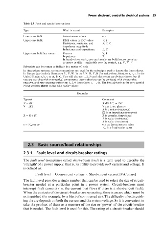
Table 2.3 Font and symbol conventions
Type What is meant Examples
Lower-case italic instantaneous values u, i
Upper-case italic RMS values or DC values V, I
Resistance, reactance, and R, XZ
impedance magnitude
Inductance and capacitance L, C
Upper-case boldface roman Phasors V, I
Impedance Z
In handwritten work, you can't really use boldface, so use a bar
or arrow or tilde ± preferably over the symbol, e.g. ~ V, V, ~ V.
Subscripts can be roman or italic; it is a matter of style
In three-phase systems, various conventions are used for the subscripts used to denote the three phases.
In Europe (particularly Germany): U, V, W. In the UK: R, Y, B (for red, yellow, blue), or a, b, c. In the
United States: a, b, c or A, B, C. You will also see 1, 2, 3 used: this seems an obvious choice, but if
you are working with symmetrical components these subscripts can be confused with the positive,
negative, and zero-sequence subscripts 1, 2, 0 (sometimes , , 0). The best advice is to be very careful!
Never confuse phasor values with scalar values!
Examples
Typeset Comment
V RI RMS AC; or DC
V jXI V and I are phasors
X is a scalar (reactance)
jX is an impedance (complex)
Z R jX Z is complex (impedance)
R is scalar (resistance)
X is scalar (reactance)
u V m cos ot u is an instantaneous value
V m is a fixed scalar value
2.3 Basic source/load relationships
2.3.1 Fault level and circuit-breaker ratings
The fault level (sometimes called short-circuit level) is a term used to describe the
`strength' of a power supply: that is, its ability to provide both current and voltage. It
is defined as:
Fault level Open-circuit voltage Short-circuit current [VA/phase]
The fault level provides a single number that can be used to select the size of circuit-
breaker needed at a particular point in a power system. Circuit-breakers must
interrupt fault currents (i.e. the current that flows if there is a short-circuit fault).
When the contacts of the circuit-breaker are separating, there is an arc which must be
extinguished (for example, by a blast of compressed air). The difficulty of extinguish-
ing the arc depends on both the current and the system voltage. So it is convenient to
take the product of these as a measure of the size or `power' of the circuit-breaker
that is needed. The fault level is used for this. The rating of a circuit-breaker should