
Page 47 - Power Electronic Control in Electrical Systems
P. 47
//SYS21/F:/PEC/REVISES_10-11-01/075065126-CH002.3D ± 37 ± [31±81/51] 17.11.2001 9:49AM
Power electronic control in electrical systems 37
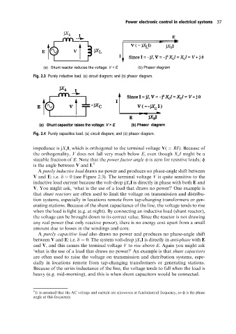
Fig. 2.3 Purely inductive load. (a) circuit diagram; and (b) phasor diagram.
Fig. 2.4 Purely capacitive load. (a) circuit diagram; and (b) phasor diagram.
impedance is jX s I, which is orthogonal to the terminal voltage V( RI). Because of
the orthogonality, V does not fall very much below E, even though X s I might be a
sizeable fraction of E. Note that the power factor angle f is zero for resistive loads; f
is the angle between V and I. 5
A purely inductive load draws no power and produces no phase-angle shift between
V and E: i.e. d 0 (see Figure 2.3). The terminal voltage V is quite sensitive to the
inductive load current because the volt-drop jX s I is directly in phase with both E and
V. You might ask, `what is the use of a load that draws no power?' One example is
that shunt reactors are often used to limit the voltage on transmission and distribu-
tion systems, especially in locations remote from tap-changing transformers or gen-
erating stations. Because of the shunt capacitance of the line, the voltage tends to rise
when the load is light (e.g. at night). By connecting an inductive load (shunt reactor),
the voltage can be brought down to its correct value. Since the reactor is not drawing
any real power (but only reactive power), there is no energy cost apart from a small
amount due to losses in the windings and core.
A purely capacitive load also draws no power and produces no phase-angle shift
between V and E: i.e. d 0. The system volt-drop jX s I is directly in anti-phase with E
and V, and this causes the terminal voltage V to rise above E. Again you might ask
`what is the use of a load that draws no power?' An example is that shunt capacitors
are often used to raise the voltage on transmission and distribution systems, espe-
cially in locations remote from tap-changing transformers or generating stations.
Because of the series inductance of the line, the voltage tends to fall when the load is
heavy (e.g. mid-morning), and this is when shunt capacitors would be connected.
5
It is assumed that the AC voltage and current are sinewaves at fundamental frequency, so f is the phase
angle at this frequency.