
Page 48 - Power Electronic Control in Electrical Systems
P. 48
//SYS21/F:/PEC/REVISES_10-11-01/075065126-CH002.3D ± 38 ± [31±81/51] 17.11.2001 9:49AM
38 Power systems engineering ± fundamental concepts
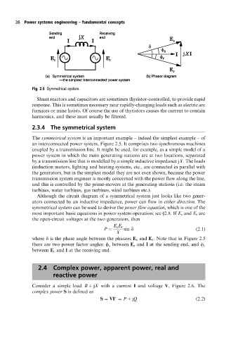
Fig. 2.5 Symmetrical system.
Shunt reactors and capacitors are sometimes thyristor-controlled, to provide rapid
response. This is sometimes necessary near rapidly-changing loads such as electric arc
furnaces or mine hoists. Of course the use of thyristors causes the current to contain
harmonics, and these must usually be filtered.
2.3.4 The symmetrical system
The symmetrical system is an important example ± indeed the simplest example ± of
an interconnected power system, Figure 2.5. It comprises two synchronous machines
coupled by a transmission line. It might be used, for example, as a simple model of a
power system in which the main generating stations are at two locations, separated
by a transmission line that is modelled by a simple inductive impedance jX. The loads
(induction motors, lighting and heating systems, etc., are connected in parallel with
the generators, but in the simplest model they are not even shown, because the power
transmission system engineer is mostly concerned with the power flow along the line,
and this is controlled by the prime-movers at the generating stations (i.e. the steam
turbines, water turbines, gas turbines, wind turbines etc.).
Although the circuit diagram of a symmetrical system just looks like two gener-
ators connected by an inductive impedance, power can flow in either direction. The
symmetrical system can be used to derive the power flow equation, which is one of the
most important basic equations in power system operation; see §2.8. If E s and E r are
the open-circuit voltages at the two generators, then
E s E r
P sin d (2:1)
X
where d is the phase angle between the phasors E s and E r . Note that in Figure 2.5
there are two power factor angles: f between E s and I at the sending end, and f r
s
between E r and I at the receiving end.
2.4 Complex power, apparent power, real and
reactive power
Consider a simple load R jX with a current I and voltage V, Figure 2.6. The
complex power S is defined as
S VI P jQ (2:2)