
Page 54 - Power Electronic Control in Electrical Systems
P. 54
//SYS21/F:/PEC/REVISES_10-11-01/075065126-CH002.3D ± 44 ± [31±81/51] 17.11.2001 9:49AM
44 Power systems engineering ± fundamental concepts
factor of unity. In general the reactive power of a fixed-reactance compensator will
not vary in sympathy with that of the load as the supply voltage varies, and a
compensation `error' will arise. In Section 2.7 the effects of voltage variations are
examined, and we will find out what extra features the ideal compensator must have
to perform satisfactorily when both the load and the supply system parameters can
vary.
2.7 Compensation and voltage control
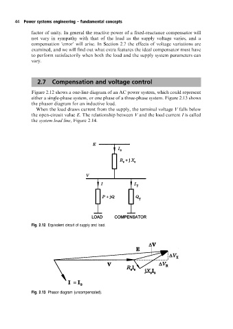
Figure 2.12 shows a one-line diagram of an AC power system, which could represent
either a single-phase system, or one phase of a three-phase system. Figure 2.13 shows
the phasor diagram for an inductive load.
When the load draws current from the supply, the terminal voltage V falls below
the open-circuit value E. The relationship between V and the load current I is called
the system load line, Figure 2.14.
Fig. 2.12 Equivalent circuit of supply and load.
Fig. 2.13 Phasor diagram (uncompensated).