
Page 423 - Power Electronics Handbook
P. 423
412 Power semiconductor circuit applications
Window Door lock Hazard
Iifl motor motor liMS
Automobile bus
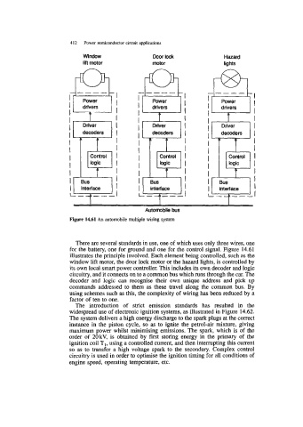
Figure 14.61 An automobile multiple wiring system
There are several standards in use, one of which uses only three wires, one
for the battery, one for ground and one for the control signal. Figure 14.61
illustrates the principle involved. Each element being controlled, such as the
window lift motor, the door lock motor or the hazard lights, is controlled by
its own local smart power controller. This includes its own decoder and logic
circuitry, and it connects on to a common bus which runs through the car. The
decoder and logic can recognise their own unique address and pick up
commands addressed to them as these travel dong the common bus. By
using schemes such as this, the complexity of wiring has been reduced by a
factor of ten to one.
The introduction of strict emission standards has resulted in the
widespread use of electronic ignition systems, as illustrated in Figure 14.62.
The system delivers a high energy discharge to the spark plugs at the correct
instance in the piston cycle, so as to ignite the petrol-air mixture, giving
maximum power whilst minimising emissions. The spark, which is of the
order of 20kV, is obtained by first storing energy in the primary of the
ignition coil TI, using a controlled current, and then interrupting this current
so as to transfer a high voltage spark to the secondary. Complex control
circuitry is used in order to optimise the ignition timing for all conditions of
engine speed, operating temperature, etc.