
Page 418 - Power Electronics Handbook
P. 418
Electrical machine control 407
An overload condition will now feed back field excitation and will be
self-sustaining, the characteristics of the alternator being modified as
shown in Figure 14.57(c). The similarity of Figure 14.57 to Figure 14.2
should be noted.
Another problem encountered with self-excited machines, which does
not occur with separate excitation, is that of starting. When the alternator
first runs up to speed, its output voltage is very low, being caused primarily
by residual field flux, and it will be too small to operate the thyristor gate
drive system, so that the thyristors will be held off and the machine will not
be excited. To overcome this it is usual to apply continuous gate drive to
the thyristors during the period that the alternator output is below a certain
critical value. The easiest way of doing this is by a small normally closed
relay connected between the anode and gate of the thyristors.
Alternatively, a static control system may be used, one type being shown in
Figure 14.58. When the a.c. line voltage from the alternator output is low,
A.C. line
k
I I
To thyristor
on exciter
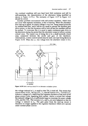
Figure 1458 Static start-up circuit for an alternator excitation system
the voltage induced in L3 is small so that TH1 is held off. This means that
current flows via D1, the top of L1, L4 and the bottom of b. Current in L4
induces a voltage in L5 which fires the regulator thyristors at the start of the
phase-control cycle, supplying field current. Above a certain line voltage
the induced voltage in L3 is sufficiently large to overcome the zener voltage
of D4 and fire TH1. The currents in L1 and b are now balanced so that no
voltage is induced in L5. The gate pulse from the start-up circuit is
therefore no longer applied to the regulator thyristors which now operate
under normal phase control.