
Page 413 - Power Electronics Handbook
P. 413
402 Power semiconductor circuit applications
were a motor although, because of the low efficiencies involved, this
method of control is again limited to small motors.
Summarising the above, it can be seen that basically there are only two
systems of speed control, (1) where the stator field speed is fixed, the slip
being variable, and (2) where the stator speed is variable, the slip being
small and relatively constant. The first method is inefficient. Voltage-
control schemes are used in small systems with fan-type loads, or to
provide constant torque over a limited range. To reduce dissipation in
larger motors external eddy current clutches may be used. The efficiency of
variable-slip systems may be increased by incorporating a form of slip-
recovery scheme, but this necessitates the use of a wound rotor induction
motor with associated slip rings and brushgear, which can make it
unsuitable for certain applications, for example operation in hazardous
atmospheres.
The most promising control system for a.c. motors is a variable-
frequency drive. A cage rotor can now be used and efficiency over the
whole speed range is also high. Such systems are normally the most
expensive, but if a drive is required to provide a constant torque output for
wide speed variations and the motor is located in an inaccessible position,
variable-frequency control of a cage rotor machine is often the only
practicable system.
14.3.4.3 Synchronous motor excitation and control
As stated earlier, the speed of a synchronous motor can only be controlled
by means of frequency variation. Changing the rotor field does not affect
the motor speed but does change the power factor that it presents to the
supply. Since the field of the motor is mounted on the rotor, it is necessary
to provided sliprings and brushes if the field excitation is to be supplied
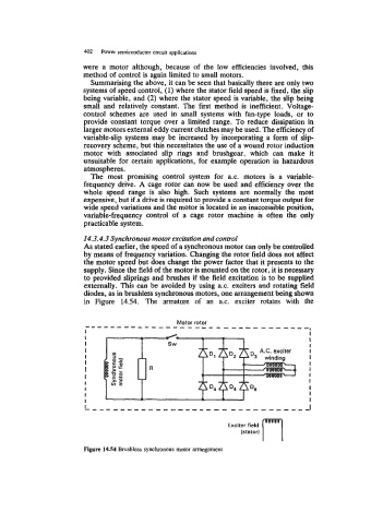
externally. This can be avoided by using a.c. exciters and rotating field
diodes, as in brushless synchronous motors, one arrangement being shown
in Figure 14.54. The armature of an a.c. exciter rotates with the
I I
I I
I I
I I
I 4 I
I I
I R I
I I
I I
I I
I - I
I I I
rl
Exciter field
(stator)
Figure 14.54 Brushless synchronous motor arrangement