
Page 412 - Power Electronics Handbook
P. 412
Electrical machine control 401
1 I-s-4
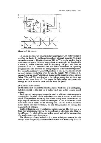
Figure 1453 Slip recovery
A simple sliprecovery scheme is shown in Figure 14.53. Rotor voltage is
rectified by diodes D1 to D4 and smoothed, although capacitor C, is not
normally necessary. Thyristor inverter THI to TH, can be used to feed a
controlled amount of the rotor energy back to the supply. As described in
Chapter 9, unlike inverters used in frequency changers, this inverter
connects to an ax. reference line AB which determines its operating
frequency and also provides the energy required to turn off the thyristors.
For example, suppose TH1 and TH, are fired at time to. The thyristors turn
on and remain conducting even though the supply AB reverses at tl,
energy being fed from VB to the a.c. lines over this negative voltage period.
When TH2 and TH3 are fired at t2 the voltage across the previous pair
reverses and turns them off. The longer the firing delay, the greater the
energy fed back from the rotor and the lower its speed.
(4) External clutch control
In this method of control the induction motor itself runs at a fixed speed,
but it is coupled to the load via a clutch which acts as the variable-speed
system.
Eddy current clutches are frequently used, in which an electromagnet is
connected to the shaft of the induction motor and is rotated at the fixed
speed. This produces a rotating field whose strength can be controlled by
adjusting the coil current of the electromagnet. A disc is connected to the
load shaft and is placed in the rotating field. Due to normal induction
motor action the disc will rotate, the slip being adjusted by varying the
magnetic field strength.
In effect there are now two induction motors in series. The first runs at a
fixed (low slip) speed, whereas the second runs at adjustable slip. Clearly,
the efficiency (l-slip) Will be poor at low speeds and will be less than that
of a single motor with slip control.
The advantage of using a clutch is that, since it dissipates most of the slip
energy, it can be specially constructed to lose this heat more easily than if it