
Page 417 - Power Electronics Handbook
P. 417
406 Power semiconductor circuit applications
shows several arrangements for alternator excitation, in all cases the
regulator converting the input supply, if it is a.c., into d.c., and regulating
the amount of the field excitation so as to maintain the output voltage
constant, at a predetermined value, irrespective of the load on the
machine. Figure 14.56(a) illustrates the simplest arrangement, which is
used for smaller machines, the input to the regulator being derived from
the ax. output of the generator itself, these lines therefore performing the
dual role of power supply and sensing for feedback voltage control. The
regulator is normally a half-controlled single-phase thyristor bridge
although half-wave circuits, using a single thyristor and a free-wheeling
diode across the field, may be used. For larger machines the arrangement
of Figure 14.56(b) is preferred, the regulator now controlling the field of an
auxiliary exciter, its armature being mounted on the rotor and supplying
the generator field through a rotating rectifier bridge. Both the above
systems can be operated from an external supply if it is available, Figure
14.56(c) showing such a system for a large turbo-generator. The feedback
line from the generator output is now required only for voltage-sensing
purposes and carries no power.
The action of a thyristor regulator, when used in an alternator excitation
system, is very similar to usual phase-control systems employed in
controlled rectification. The greater the delay angle (Y in the firing of the
thyristors during a half cycle, the lower its d.c. output and therefore there
is a fall in alternator voltage, and vice versa. There are several other
considerations which modify the simple control loop shown in Figure
14.56. For instance, it is often desirable to introduce a droop in the output
voltage characteristic such that the terminal voltage falls with load, to
enable better load sharing between parallel-connected machines. Similar-
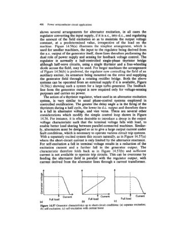
ly, alternators must be designed so as to give a large output current under
fault conditions, which is necessary to operate various circuit trip systems.
With a separately excited system this occurs naturally, as in Figure 14.57(a)
where the short-circuit current is only limited by the alternator reactance.
For self-excitation a fall in terminal voltage results in a reduction of the
excitation current and a further fall in the generator output. The
characteristic therefore folds back as in Figure 14.57(b) and sufficient
current is not available to operate trip circuits. This can be overcome by
feeding the alternator field in parallel with the regulator output, with
current derived from the alternator lines through a current transformer.
0 1-y p*\?\
c -
c
C
I
> d
I
8
I
4-
Current I I Current I I Current
Full load Full load Full load
(a) (b) (C)
Figure 14.57 Generator characteristics up to short-circuit conditions: (a) separate excitation;
(b) self-excitation; (c) self-excitation with current boost