
Page 414 - Power Electronics Handbook
P. 414
Electrical machine control 403
synchronous motor field winding, the a.c. output from the exciter being
rectified by rotating diodes D1 to D6 before being fed to the motor field.
During run-up switch Sw is open and the field windings are shorted
through resistor R, the a.c. exciter field being open circuit. When the
machine nears synchronism centrifuge switch Sw closes, the exciter field
now becoming energised so that d.c. is applied to the synchronous motor
field and it locks onto the rotating stator field.
Synchronous
motor field
Exciter field
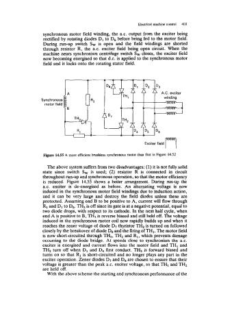
Figure 14.55 A more efficient brushless synchronous motor than that in Figure 14.52
The above system suffers from two disadvantages: (1) it is not fully solid
state since switch Sw is used; (2) resistor R is connected in circuit
throughout run-up and synchronous operation, so that the motor efficiency
is reduced. Figure 14.55 shows a better arrangement. During run-up the
ax. exciter is de-energised as before. An alternating voltage is now
induced in the synchronous motor field windings due to induction action,
and it can be very large and destroy the field diodes unless these are
protected. Assuming end B to be positive to A, current will flow through
R1 and D1 to D6. TH3 is off since its gate is at a negative potential, equal to
two diode drops, with respect to its cathode. In the next half cycle, when
end A is positive to B, TH3 is reverse biased and still held off. The voltage
induced in the synchronous motor coil now rapidly builds up and when it
reaches the zener voltage of diode D7 thyristor TH2 is turned on followed
closely by the breakover of diode D8 and the firing of TH1. The motor field
is now short-circuited through THl, TH2 and R1, which prevents damage
occumng to the diode bridge. At speeds close to synchronism the a.c.
exciter is energised and current flows into the motor field and TH1 and
TH2 turn off when D1 and D4 first conduct. TH3 is forward biased and
turns on so that R1 is short-circuited and no longer plays any part in the
exciter operation. Zener diodes D7 and D8 are chosen to ensure that their
voltage is greater than the peak a.c. exciter voltage, so that TH1 and TH2
are held off.
With the above scheme the starting and synchronous performance of the