
Page 409 - Power Electronics Handbook
P. 409
398 Power semiconductor circuit applications
Equation (14.10) is used to calculate the torque for supply frequencies f
=fi, f,/2 andf,llO wheref, is the frequency used in Figure 14.46 and the
results are given in Figure 14.48. From this it is evident that the available
motor torque can be readily controlled to match the load and so give any
desired operating speed. Furthermore, since the stator field speed need
only be slightly greater than rotor speed, the resultant rotor current being
just sufficient to overcome load torque, slip over the whole range can be
very small giving high efficiency. In Figure 14.48 slip is plotted along the
horizontal axis so that all the curves originate from the same point, but if
torque is plotted against speed, as in Figure 14.49, the graphs terminate at
their respective synchronous speeds.
(ii)
(b)
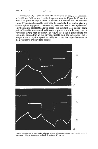
Figure 14.50 Motor waveforms for a bridge inverter using quasi-square wave voltage control:
(a) motor stalled; (b) motor on no-load; (i) voltage; (ii) current